Introduction #
I’ve recently become interested in LED matrix circuits and want to try making an equalizer.
Since it will probably take a long time to complete, I plan to divide this into multiple articles and write them as I make progress.
This time, I will implement the dynamic lighting of the LED matrix.
Let’s get started right away!
Equipment #
- Raspberry Pi Pico W
- 3mm Red LED 625nm 70-degree OSR5JA3Z74A (9 pieces)
- Carbon Resistor (Carbon Film Resistor) 1/4W 250Ω (3 pieces)
- Cables / Jumper Wires
Wiring #
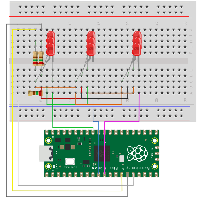
The breadboard wiring is as follows.
LED Matrix Control #
Since an LED is a light-emitting diode, it has the characteristic of resisting current flow in the reverse direction.
Of course, if it exceeds the breakdown voltage, it will break.
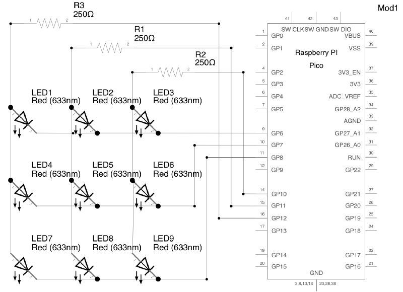
Here, by setting the output of GP10 to High and controlling the outputs of GP6, GP7, and GP8 connected to LED3, LED6, and LED9 respectively, we can control the LEDs.
For example, in the following case:
- Low:
GP6 - High:
GP10,GP7,GP8
Only LED3 satisfies the forward voltage, and the LED turns on.
With this, we can control 9 LEDs using 6 wires.
Similarly, a 4x4 matrix can control 16 LEDs, and a 10x10 matrix can control 100 LEDs.
Notes #
This time, I wrote it in C.
I wrote about setting up the C SDK environment in this article.

First is the GPIO definition.
#define PIO_1 10
#define PIO_2 11
#define PIO_3 12

#define PIO_4 6
#define PIO_5 7
#define PIO_6 8The numbers are GPIO numbers, not PIN numbers.
Since I want to adjust the brightness of the LEDs, I will use PWM dimming.
The anode will use PWM, and the cathode will use regular GPIO output.
PWM #
Initialization #
Tell the GPIO to use PWM.
gpio_set_function(PIO_1, GPIO_FUNC_PWM);Get the GPIO slice.
uint slice_num_1 = pwm_gpio_to_slice_num(PIO_1);Set a period of 256 cycles (including 0 to 255).
pwm_set_wrap(slice_num_1, 255);Set the duty cycle for the channel.
Here, I will set 0 as the initial state.
The range depends on the cycle period set with pwm_set_wrap.
pwm_set_chan_level(slice_num_1, PWM_CHAN_A, 0);
pwm_set_chan_level(slice_num_1, PWM_CHAN_B, 0);
Enable the PWM.
pwm_set_enabled(slice_num_1, true);Dimming #
After initialization, you can control the brightness using the GPIO number.
The larger the number, the higher the brightness.
The range depends on the cycle period set with pwm_set_wrap.
pwm_set_gpio_level(PIO_1, 127);GPIOs #
Initialization #
Initialize the GPIO.
gpio_init(PIO_4);Set the GPIO input/output direction.
Here, we set it to output.
gpio_set_dir(PIO_4, GPIO_OUT);Control #
Set the GPIO output voltage.
1 is High, and 0 is Low.
gpio_put(PIO_4, 1);Conclusion #
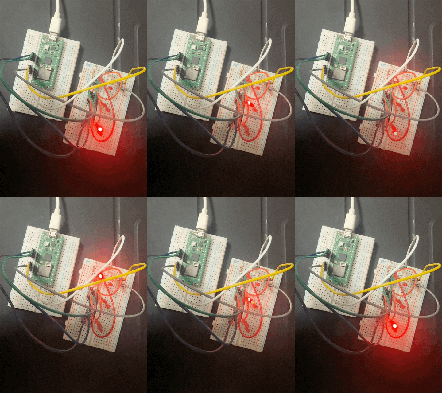
At this stage, we have achieved dynamic lighting of the LED matrix.
Next time, I plan to do wireless communication with a PC.