
Circuit Diagram #
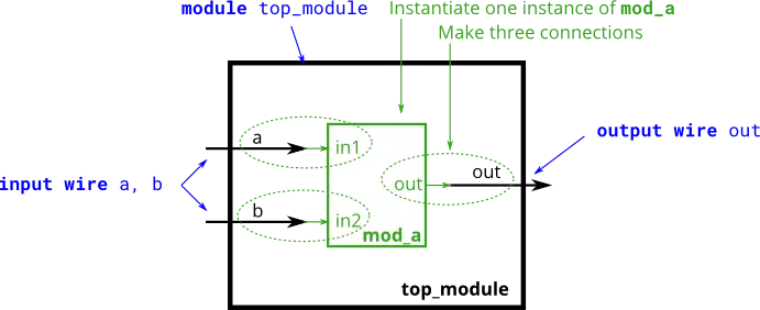
Module Code #
When connecting modules, only the ports are important. You do not need to know the code inside the module.
The module code is as follows.
module mod_a ( input in1, input in2, output out );
    // Module body
endmodule
Instances and Connections #
By Position #
mod_a instance1 ( wa, wb, wc );By Name #
mod_a instance2 ( .out(wc), .in1(wa), .in2(wb) );Example #
module top_module (
    input a,
    input b,
    output out
);

    // Create an instance of “mod_a” named “inst1”, and connect ports by name:
    mod_a inst1 (
        .in1(a),     // Port “in1” connects to wire “a”
		.in2(b),    // Port “in2” connects to wire 'b'
        .out(out)    // Port “out” connects to wire “out”
                // (Note: mod_a's port “out” is not related to top_module's wire “out”.
				// It is simply a coincidence that they share the same name)
    );

/*
    // Create an instance of “mod_a” named “inst2”, and connect ports by position:
    mod_a inst2 ( a, b, out );    // The three wires are connected to ports in1, in2, and out, respectively.
*/

endmodule